The Purpose of The Injection Mold Cooling System
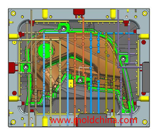
The design purpose of the cooling system is to ensure uniform cooling, as well as the shortest possible ejection time of the molded products, so as to complete the production process. Cooling design has a direct influence on product quality and molding cycle.
Cooling Location
- For materials that shrink a lot, such as PP, PE and PVC, it is better that the cooling system is deployed along the shrinkage direction of products.
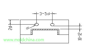
- On condition that the strength of mold material is guaranteed, the cooling should be close to the mold cavity or mold core surface as much as possible and evenly deployed around the molded product, of which the dimensional requirements are shown in the following diagram:
- When the mold adopts the inserting structure while the insert is big enough, it should be cooled separately. Ring-like cooling channels are often designed for circular mold inserts, such as the gear inserts. Large sliders need to be separately cooled, too. D = d + (1 – 2) (d refers to channel diameter)
- Each part of the mold has to be cooled in a uniform way. The BeCu alloy is often employed in cooling the structures that does not allow the design of a cooling system.
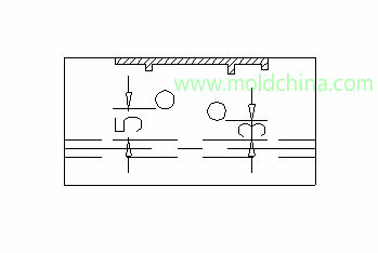
- When two cooling channels form an overhead crossing or on the same level, the minimum space between them should be 3mm if the channel width is smaller than 150, and 5mm if the width is greater than 150. See the diagram.
- Cooling design should try to avoid ejector pin, ejector sleeve, ejector guide pin, lifter, ejector, screws, etc. and the smallest clearance around them should be at least 3mm. When the mold is designed with an early ejector return, the water inlet/outlet location should be able to avoid interference with it.
- If there are more than 2 sets of cooling systems in a plastic injection mold, the water inlet/outlet location should be marked with “IN” and “OUT”, which refers to Water Inlet and Water Outlet respectively. At the same time, they should be numbered to indicate connection sequence.
Mold Cooling channel Dimensions
- Try to use the largest possible cooling channel, with the minimum being ø1/4’’. Accept the ø3/16” option when there are no other choices, but the largest cannot be larger than ø1/2”. The commonly used channels are sized ø1/4”, ø5/16” and ø3/8”. Try to keep the diameter of pipes in a cooling channel as consistent as possible, so as to ensure a uniform flow rate. In a mold, there cannot be too many joints in a single set of cooling channel, so as not to affect the cooling effect.
Positional Relationship between Cooling Channel & Mold Base
- It is preferred that water inlet/outlet are deployed along the width direction of the mold base, or 4 corner columns are needed to be added along the length direction of the mold base.
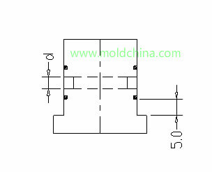
- In principle, cooling water gets in the mold from mold base, instead of connected to mold interior directly. When cooling water has to get in mold interior directly or be used to cool the sliders, a 20 – 40 clearance should be kept between mold base and hose nipple.
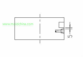
- For vertical molds, it should be avoided that the water pipes go through the clamp slots which should be at least 5mm from the cooling drilling.
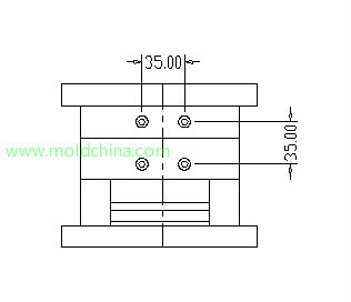
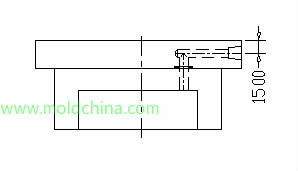
See the diagram:
- When the cooling systems of the core and cavity get in and out from the same direction, the outlets should be at least 35mm from each other.
- When mold plate is not thick enough but cooling is needed, it should be guaranteed that the cooling center is 15mm from the top of the plate. When plate thickness measures 20mm, the distance should be kept at 13mm.
Cooling Tower
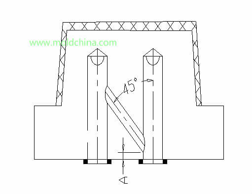
For products designed with deep cavities, to ensure thorough cooling of product, a cooling tower should be designed. When an angle hole is needed to join 2 cooling towers, the biggest angle should be no larger than 45°, and A should be no less than 3.0mm (see the diagram). Cooling tower adopts the bronze spacer, of which the dimensions are shown below:
1) 1/8″x1″x1200mm
2) 1/8″x1-1/4″x1200mm
3) 1/8″x1-1/2″x1200mm
https://youtu.be/rVBRZzbCDlc
All copyright reserved by mold company Sositar Mould


